To understand how to stop encoder failures on your top drives, you have to understand the failures themselves.
In my previous blog, we discussed some of the causes of rotary encoder failures on top drives.
In this blog, we'll dive a bit deeper and look at the failure modes themselves.
Next, let’s look at failure modes.
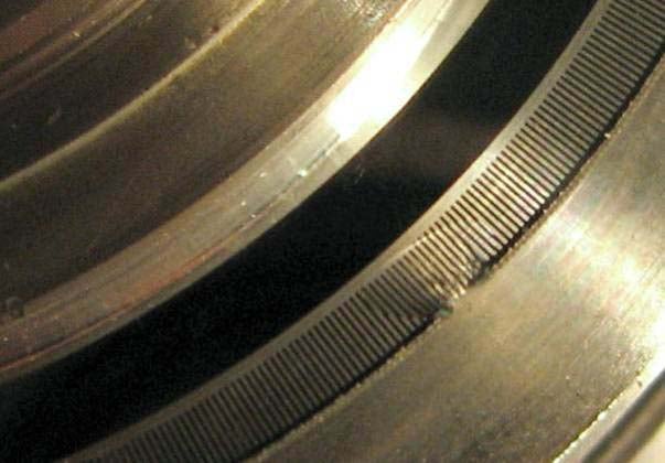
Optical electronic failure is common among optical encoders. Take a look at the photo above taken from a failed incremental encoder on a drilling application. Can you spot the problem? Typical rotary encoder construction uses optical sensors with a glass disk. Lines on the disk interrupt a light beam to a photo eye. This fragile system can easily be disrupted by dirt and water that interrupts or distorts the beam. Additionally, the glass disk of the optical sensor is very prone to cracking or shattering. (This picture shows a chip taken out of the disk when the encoder was exposed to heavy vibration). Because optical rotary encoders are often a huge liability, it is recommended that magnetic rotary encoders are used for drilling applications.
Here's another shaft encoder that we opened up after a customer asked us if we had a superior replacement model: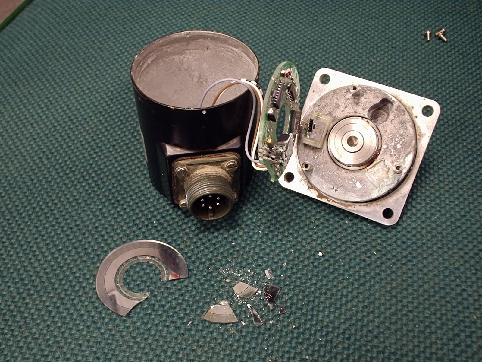 Perhaps the damage here is more clear.
With the challenge of constant vibration in rotary encoders, bearing failure is very common. Typical encoders use a tiny ball bearing to support either a solid or hollow shaft construction. These bearings frequently fail when subjected to vibration and loads caused by tethering hollow shaft encoder models, spline coupling systems or belt-driving shafted encoder models. For more information on vibration-related failures of encoder bearings, try this Wikipedia article on false brinnelling. To solve bearing-related problems, there are two schools of thought: eliminate the bearings, or make them massive. We'll discuss both of these ideas in more detail later.
The final encoder failure mode we will discuss is seal failure. Look at the rotary encoder above (green background). Note that the interior of the aluminum housing is white with corrosion from contamination. The repeated temperature cycling in drilling causes pressure on the shafted encoder seals which then give way. More temperature cycles draw dirt, dust, water and oil (contamination) into the optics and bearings, causing optical system or bearing failure. To help reduce the risk of seal failure, labyrinth and combination seals should be used instead of simple rubber washers. This greatly decreases ingress of water and dirt into the bearings. Likewise, a no-bearing encoder can withstand huge amounts of contamination; as long as the contamination doesn't destroy or block the sensor. Magnetic sensors can really improve top drive encoder reliability because they can see through dirt, dust, oil and condensation.
All these encoder failures will lead to drive tripping, or inaccurate positioning. That means inactive rigs, resulting in lost profits.To learn more about the solutions for top drive encoders, follow the next in our series of blog posts on top drive encoders, or download our white paper: