Understanding how optical encoders work, especially rotary encoders, can help you eliminate (and understand) encoder problems on your drilling rigs.
First, the basics:
Nearly all optical encoders work in fundamentally the same way. A LED (usually infrared) shines through an encoding disk with lines which interrupt the beam of light to a photosensor. (A rare few bounce the light off an reflective encoder disk with light/dark areas instead of passing the light through, but the other encoder principles are identical).

But it's not quite as simple as passing a beam through a encoder disk in the real world and getting a square wave train of pulses output.
LED light beams diverge, or spread out, so this would make multipler "fuzzy" shadows on the optical encoder sensor. What the encoder sensor wants to see is clear on/off changes when the lines pass in front of the encoder LED beam. To begin to solve this problem, encoder manufacturers add lenses over the LED. This makes the light beams nearly parallel.
The rotary encoder disk contains the lines which interrupt the beam. Again, ideally, the encoder manufacturer wants the lines to be as sharp as possible, to produce clear transitions from dark-to-light and light-to-dark on the encoder sensor. Encoder manufacturers have used glass encoder disks for years in machine tool encoders. The lines can be placed with great accuracy on the glass disk. However, glass encoder disks have serious durability issues in rugged applications like oil drilling. So manufacturers of optical rotary encoders for industrial applications have switched to metal disks with holes etched through, or plastic disks, or super-reinforced glass.

Each of these rotary encoder disk types have limitations. The super-reinforced glass encoder disk still is glass, and can fail under the heavy shock and vibration of drilling or other tough applications. Plastic encoder disks flex under vibration, causing potential errors in velocity or position measurement. The metal encoder disks can also flex, and the tiny encoder disk holes can become clogged with dust or debris.
Speaking of dust and debris, they are a huge problem for all optical encoders, no matter what the disk type. They can block the light just like a line on a rotary encoder disk, fooling the encoder sensor system. This creates velocity errors for incremental encoders, and position errors for absolute encoders.
Water? Did someone say liquids? A single droplet of liquid on the rotary encoder disk acts like a lens, bending the light. Now the encoder position is not measured accurately. To make matters worse, if the optical encoder heats up, the moisture can evaporate! Now the quadrature encoder that was malfunctioning starts working again!
Now let's look at what happens on the other side of the rotary encoder disk.
On this side of the encoder disk in most optical rotary encoders is a "mask", which is a pattern of lines that closely match the disk. By passing the light through the encoder mask, the on/off transitions are sharpened. (Again, the goal of optical encoders is to clearly differentiate between light and dark areas to measure movement accurately).
The light then falls on a set of encoder photo-detectors. These are typically silicon semiconductor cells closely related to solar cells. More light allows more electrons to flow; darkness prevents electron flow. Here's a picture of a photocell; unfortunately in this rotary encoder, the spinning disk contacted the encoder sensor, destroying it and leaving a visible mark.

So with all the effort to make clear light-to-dark transitions, you might think the encoder photosensor output would be a square wave as shown in the first illustration above. But it is not--it is a sine (and cosine) wave.

Manufacturers of most rotary encoders add comparator circuits to create square waves in quadrature encoders aka. incremental encoders.
Now the output from the comparators is nearly ready for customer use. Most manufacturers of incremental encoders add a line driver chip to the output. The purpose of the encoder line driver chip is to provide differential quadrature output (A, A/, B, B/), provide enough power to drive the encoder signal down long wires, and protect the encoder from wiring errors.
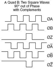
Most rotary encoders now also add a marker pulse with a complementary signal, called (Z and Z/), index, or many other titles. For more information on rotary encoder signals and encoder wiring information, see our blog on preventing encoder failures.
Absolute rotary optical encoders are similar to optical rotary incremental encoders, but they have more lines, and more sensors. In a future blog, we'll take a look at absolute optical encoders and their differences from, and similarities to, incremental encoders.
For more information on eliminating (optical) encoder failures in oil drilling rigs, download our white paper